Time Clock Contactor Wiring Diagram
Hager ezn002 delay off timer. Like 220/ 221 said, the time clock control power to the photo eye and the photo eye controls the contractor.

Hager Esc225 Contactor Wiring Diagram at Wiring
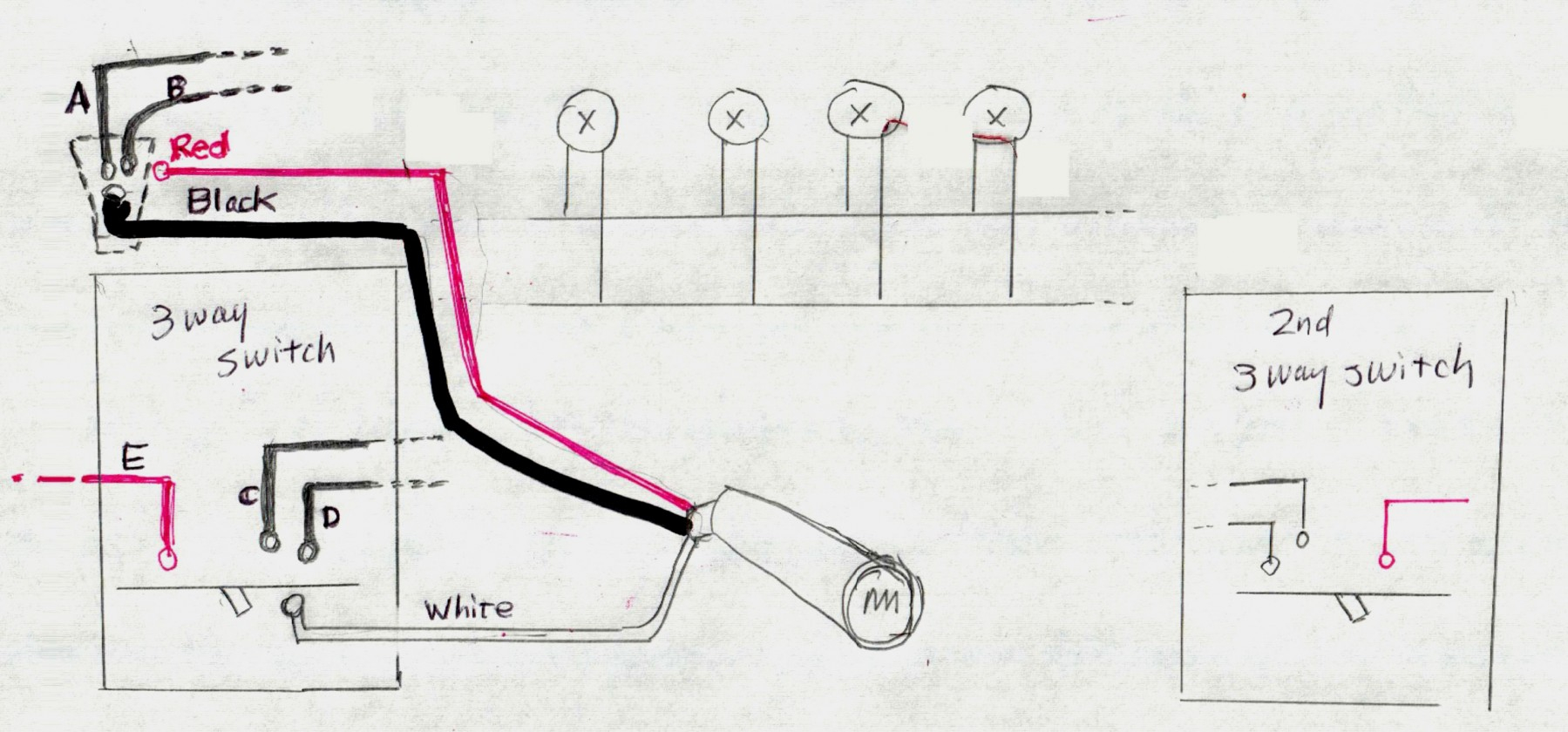
They want these to be controlled by a time clock an photo cell but also run through a key switch and contactor.

Time clock contactor wiring diagram. Photocontrols need to be hot all the time. How to wire t timer. I was tutoring several students with basic wiring this week so i made this video for them to review.
The contactor handles the electrical vol. Contactor timeclock wiring diagram contactor for pool pump timer diy home improvement forum. In operation, photocontrol turns on the lights at dusk (time clock is already on) then the time clock turns them off at 3am.
Wiring diagram reference 2p 4p 2p pole. 35 latest hager 4 pole contactor wiring diagram stephan fuchs. Time clock and photocell wiring diagram.
There are 5 new circuits to run in total. This would allow you to turn the contactor on/off with a single pole switch. Put the time clock contacts after the photocontrol in series with the red lead.
A pool pump timer interrupts the electric circuit powering the pump motor during off use periods. Contactor and photocell wiring diagram pdf wiring diagrams click photocell wiring diagram pdf uploaded by anna r. Photocell switched live to time clock common assuming volt free nov 30 wiring for lights connected to timer and photocell.
This is assuming the timer contact is maintained the whole time you want your lights to be on. They want these to be controlled by a time clock an photo cell but also run through a key switch and contactor. If you where not in class this may be confusing.
Unique schematic symbol switch diagram wiringdiagram diagramming diagramm visuals visualisation gra well pump pressure switch submersible pump well pump electrical diagrams motor phase pump with manual automatic float court esquemas electricos diagrama de instalacion electrica proyectos electricos dol starter circuit diagram wiring single phase. Multiple switches and a time clock would require momentary contact switching. Each component ought to be set and linked to other parts in specific manner.
Contactor wiring diagram wiring diagrams lose contactor wiring diagram additionally wiring diagram provides you with the time body in which the assignments are for being finished. So when the photocell turns on it disconnects the time clock output and energises the lighting contactor. 20a clm lighting contactor typical photocell 2w acc · 20a clm lighting contactor.feb 09, · photocell with timer and contactor wiring, photocell with timer wiring diagram, time clock photocell override switch drawing, lights timer contctor auto manual digaram, lighting time clock diagram, photocell with time clock, outisde light time clock, photo electric cell and time clock.
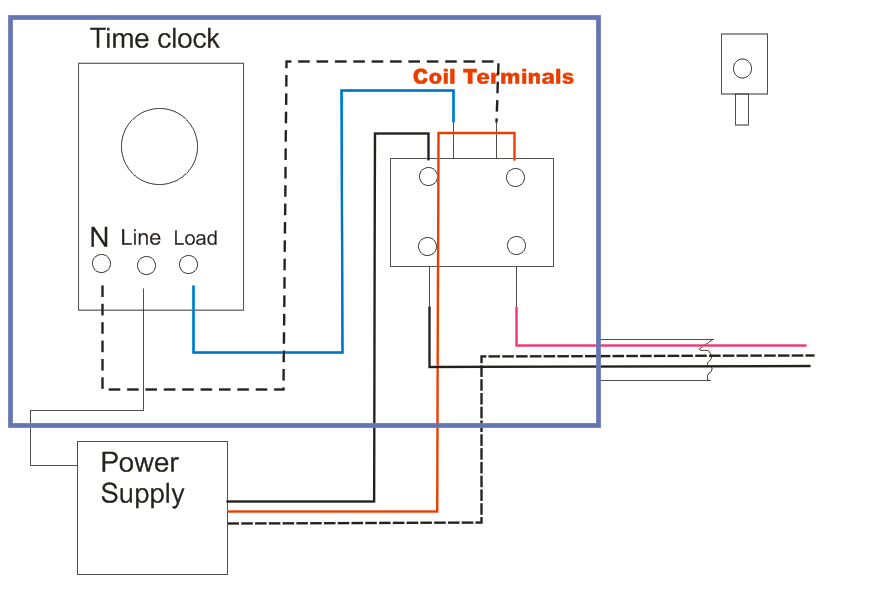
(clock motor is connected to same constant power as the p/c) the load side of the time clock runs to contactor (s) for fixtures that are meant to shut off at a specified time. The photo eye load side (usually the red leg) supplies voltage to your contactor coil. With this sort of an illustrative manual you will be able to troubleshoot avoid and complete your tasks with ease.
3405a single wiring with diagram timer phase contactor. Madcomics timer switch wiring diagram hager surface mount 24hr analog eh 010 instruction manual pdf to connect 225 eh711 24hrs time contactor digital eg103b e welcome electronic lighting i need it is wall. Set the time clock to come on during daylight and off at 3am.
Hager timer switch wiring diagram. How to wire a time clock control 2 circuits intermatic wh40 water heater real module precision multiple controls official timer light switch circuit wiring contactor with an mcb and rccd combination boilers hager eh711 24hour plug typical diagram for fully electrical education electricians training how to wire a time clock time clock to control […] It shows the components of the circuit as simplified shapes and the capacity and signal links amongst the devices.
It’s been some time since i wired contactors and was just looking for some advice on it or if someone could provide a wiring diagram i would be very grateful thanks in advance • disconnect power at the circuit breaker(s) or moving the clock hands can damage the timer. If necessary, press the mode button repeatedly until the words set and clock appear in the upper area of the display.
With your control circuit, feed the time clock first, then the photo eye. Accesory 47 is for two wire control. Last the photocell output should be connected to the relays coil.
Warning risk of fire or electric shock. The contactor will pull in when it has the correct voltage across a1 and a2. Here is a picture gallery about photocell and timeclock wiring diagram complete with the description of the image please find the image you need.
The black line wire connects to line voltage from the panel the red load wire. Contactor wiring diagram with timer pdf teknik listrik teknik. The line terminal of the time clock.
Contactor (s) coil (s) that run dusk to dawn lighting (selected fixtures for security lighting) 2.
Tork Wiring Schematic for Lighting Contactor and Photocell

Photocell Wiring Diagram Wiring Diagram

Wiring Diagram For Timer And Contactor

Photocell On Time Clock Off Wiring Diagram The Wiring
Time Clock And Contactor Wiring Diagram Complete Wiring


It has been a time!. I need you to verify some things for

Tork Time Clock Wiring Diagram Style Guru Fashion

Intermatic Photocell Wiring Diagram Download

Wiring Diagram For Time Clock And Contactor

Photocell And Timeclock Wiring Diagram Wiring Diagram
Lighting Contactor With Photocell Wiring Diagram
Wiring Diagram For Time Clock And Contactor Irish

Hager Esc225 Contactor Wiring Diagram at Wiring

I have 3 400 watt MH lights 208 volts that I want to have
Wiring a contactor with an mcb and rccd D.I.Y. Kit UK420


Lighting Contactor Wiring Diagram With Photocell
Time Clock Photocell Lighting Contactor Wiring Diagram
Electrical Education Electricians Training How to wire
GRay again. What would make a mechanically held latch and
